|
HeatersPlus.com Questions? 1-800-442-2581 |
Our secure online ordering website: www.MorElectricHeating.com.
|
| Home | Ordering | Contact Us | Heaters | Controls | Accessories | Search | ||
|
HeatersPlus.com Questions? 1-800-442-2581 |
Our secure online ordering website: www.MorElectricHeating.com.
|
| Home | Ordering | Contact Us | Heaters | Controls | Accessories | Search | ||
Warren Technology CBK Custom Built Electric Duct Heaters for Commercial HVAC Systems
We are an authorized distributor for
Warren Technology
Warren Technology produces Custom Built Electric Duct Heaters for installation in commercial HVAC systems. Warren heaters are engineered for reliability and safety, and are specifically designed not to exceed safe operating temperatures. Custom built electric duct heaters are safety tested and listed by Underwriters Laboratories (UL) and the Canadian Standards Agency (CSA), and meet National Electric Code (NEC) requirements. Warren's custom built electric duct heaters have several advantages over alternative heating products.
Completely computerized CAD/CAM engineering and our modern production facility ensures product quality, design flexibility and quick delivery. Virtually unlimited KW capacities and element size combinations ensure that any requirement can be met. All Warren heaters employ proprietary technology known as the "Calculated Wire Temperature Method" to ensure that all heater components operate safely within their electrical and temperature requirements.
Warren manufactures a number of heaters in a variety of shapes, sizes and configurations, particularly in its unitary product line. Unitary electric "insert heaters" and "outlet mounted duct heaters" are used in smaller residential and light commercial HVAC systems. The company offers Unitary heaters as a substitute accessory item used in major equipment manufacturers air handling units. Specific Unitary heater designs have been safety tested and listed under one or more of the following consumer testing agencies: Underwriters Laboratory (UL), Canadian Standards Agency (CSA).
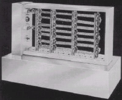
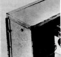
INTEGRAL PANEL SLIP-IN MOUNT
![]() UL Listed
UL Listed
![]() CSA Certified
CSA Certified
·
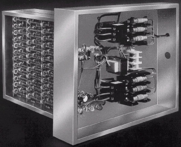
The Warren Modular Duct Heater offers the most modern engineering design, with maximum versatility and dependability.·
Elements are computer selected by the calculated wire temperature method to insure that exact electrical and heat characteristics are achieved.·
The element support ceramics are held by the unique element support rack permitting them to expand without cracking or breaking.·
The computer-selected elements always utilize every necessary ceramic element support insuring that the elements evenly fill the open area of every duct.·
Virtually unlimited KW capacities and element size combinations insure that any requirement can be met.·
Multiple airflow positions are available assuring maximum position flexibility.·
Heaters for all voltages can be provided.·
Heaters are U.L. listed for zero clearance and meet all applicable requirements of the National Electric Code (N.E.C.).·
Heater frames and boxes are constructed of 20 gauge or heavier galvanized steel.·
A hinged control panel cover for all units with fuses, door disconnects, or manual limits is standard.·
De-energizing magnetic contactors are standard on all heaters.·
Heaters are available as Slip-In of Flanged Mount.·
Factory pre-wiring of accessory components eliminates costly field installation.·
A specific wiring diagram is furnished for every heater regardless of the accessories.·
A broad range of control options and accessories is offered to meet all needs and allow true customizing of heater requirements.·
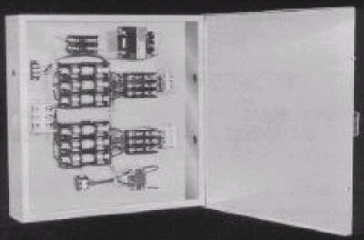
Completely serviceable without removal from the installation.REMOTE PANEL (V1)
·
Control Section can be mounted in any convenient location.·
Disconnecting Contactors meet U.L. requirements for remote location.·
Connections between Control panel and Heater Section are easily made through the use of factory installed terminals.·
Control Panel components are completely factory wired and only the connections made between the panel and the heater need to be field connected.·
Heater Section available as Slip-In or Flanged mount.·
All accessories available for Custom Built Heaters are available for Remote panel Heaters.·
All construction features of the Custom Built Heaters are incorporated in the Remote Panel Heater.BOTTOM MOUNT (V8)
·
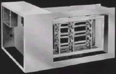
U.L. LISTED AS bottom Mount Heater.·
Provides maximum ease of serviceability in limited installation space.·
Controls are accessible without the need to remove the heater.·
Factory pre-wiring of accessory components eliminates costly field installation.·
All construction features of the Custom Built Heaters are incorporated in the Bottom Mount Heater.FLANGED MOUNT (v2)
·
Flanged Mount provides maximum duct rigidity.·
Design allows virtually unlimited duct size match-ups.·
Standard 1" flange matches standard SMACNA duct flange.·
Deeper flange depth available where required.·
Heater flange and boxes are constructed of 20 gauge or heavier galvanized steel.·
Permits close coupling to air handling device when required.·
All control accessories as listed are available.HEATER DESIGN FEATURES
UNIQUE ELEMENT DESIGN
Warren Technology’s design criteria for heating element selection is based on actual element operating temperature.
Warren selects all elements by its exclusive "Calculated Wire Temperature Method," a method which insures that elements in heaters operate within the designed electrical and temperature requirements, and do not exceed the melting point of the alloy
even in still free air.The system allows Warren to determine the exact operating temperature of the heater elements in a specific condition. The elements are designed to operate below the maximum allowable temperature recommended by the element alloy manufacturer under the worst possible condition. This process eliminates most problems associated with hot spots in heaters caused by poor air distribution.
This method of design allows Warren Technology to predict operating temperatures and life spans of any given element in our duct heater product line and has resulted in a zero failure rate on units installed in the field for over the past 10 years.
COMPUTERIZED SELECTION
A Computer Selection Program developed after years of research insures that Warren Technology's heaters can meet an infinite number of size and voltage requirements. Utilizing a computer insures that every heater is going to perform consistently. Warren can tell exactly how the element is going to operate and how long it can be expected to last under specific requirements. Computer selection of component parts permits complete compatibility utilizing a manufacturing process where all duct heaters are produced from standard components incorporated in an exclusive modular design. This computer selection method is applied on all three basic product line categories, including Custom Built (CB), Stock-Line (SL), and Special Product (SP) electric duct heaters.
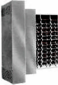
CERAMIC SUPPORT SYSTEM
Warren Technology, utilizes an element support system, which permits the ceramic element supports to expand and contract freely without cracking or breaking. The heavy support frame completely surrounds the individual ceramic insulators while allowing the insulators to "float" freely, eliminating any binding. The modular concept lends itself to selection of predetermined distances between the exclusive support frames thus assuring optimum element support.
HEATER FRAME
Warren Technology employs the most modern technology available in the industry to construct the heater frames and boxes. Predetermined optimum element support spacing allows the modular concept to offer the choice of virtually any element rack size combination, and yet utilize the cost savings of volume production. All frames and boxes are constructed of 20 gauge, or heavier, hot dipped galvanized steel. The frame is integrally tied to the control box providing solid one piece construction for ease of installation. Additionally, this construction allows almost any location relationship between the element rack and control box giving unlimited sizing flexibility.
PERMANENT ELECTRONIC FILE
A permanent electronic file is made for each control panel. The electronic file is retained as a future reference. Having this record on file allows Warren Technology to produce identical heaters at a later date, offer precise engineering assistance to the installing contractor or service personnel should it be required, or supply replacement parts identical to those originally furnished if necessary. This is a feature offered exclusively by Warren.
ENGINEERING INFORMATION
U.L. AND N.E.C. REQUIREMENTS
The information listed is offered as a guide for electric duct heater requirements. It is based on the National Electric Code (N.E.C.) and Underwriters Laboratory (U.L.) Space Heating Standard No. 1096. Although this is intended to assure that these heaters are manufactured to meet N.E.C. and U.L. requirements, local electrical codes should be considered for compliance.
Over temperature Protection — U.L. and N.E.C. requires the manufacturer to provide two types of over temperature protection. Warren supplies as standard a disc type automatic reset limit, which deenergizes the heater in the event of overheating. A secondary limit, consisting of a replaceable fuse link, is provided, which operates at a higher temperature and de-energizes the heater in case of failure of the primary limit.
Over current Protection — U.L. and N.E.C. require that a heater in excess of 48 AMPS be subdivided into circuits of less than 48 AMPS each and built-in fusing be provided by the heater manufacturer. The over current device (fuse or circuit breaker) must be rated for 125% of the circuit load and limited to 60 AMPS maximum. U.L. requires the over current protective devices be supplied by the heater manufacturer.
Loss of Air Flow Protection — U.L. and N.E.C. require that a method be provided to prevent the duct heater element from being energized unless the fan circuit is energized and airflow is present. Warren provides a choice of 4 integral methods to meet this requirement: Fan Connection, Fan Control Relay, Fan Interlock Relay and Air Pressure Switch.
Transformer Protection — Transformers are required for heater operation u n less an external control voltage source is available and where the heater power voltage is different from the control voltage. U.L. requires transformers to have primary over current protection. The Class II transformer meets this requirement with built-in protection while all other non-Class 11 transformers supplied are primary fused externally. Secondary transformer fusing is available as an option to protect the control circuit but is not required by U.L.
Equipment Grounding — U.L. requires that a grounding lug be installed by the manufacturer for field wiring connection. All Warren heater control panels contain a U.L. approved grounding lug.
Disconnect Location — N. E.C. requires an equipment disconnect switch be installed at or within sight of the heater. Warren offers factory installed disconnect switches (or they may be field supplied to comply with this requirement).
Contactors —U.L. requires that the heater manufacturer supply the contactors as a built-in integral component of the heater.
INSTALLATION INFORMATION
Good installation practice dictates certain guidelines be followed. Although the guidelines listed are general recommendations, Warren has the unique ability to custom design heaters to specifications involving unusual applications. Consult the factory for deviations to usual installation practices.
·
Always consult local codes for compliance.·
Follow SMACNA guides and recommendations.·
Install heaters with the air flow in the proper direction as indicated by the arrow.·
Make all electrical connections per U.L. and N.E.C.·
The heater should be installed 4ft. from the air handler unless designed for internal mount or close coupling.·
Provide minimum 4ft. clearance from elbows, transitions, extractors, or similar turbulence producing devices.·
Reinforce duct where necessary to support the weight of the heater and prevent sagging.·
Allow sufficient clearance for servicing and removal if necessary. Units greater than 50 KW should be controlled by a system with a recycling feature that will not allow all steps to be energized simultaneously. The absence of such a device causes severe damage to the equipment.·
The use of discharge air sensing devices to control this heating unit is not factory recommended and may void the warranty.PRIMARY INTEGRAL COMPONENTS – ACCESSORY OPTIONS
U.L. LISTED ELECTRIC DUCT HEATERS
Pictures shown are representative only and may vary with requirements and availability.
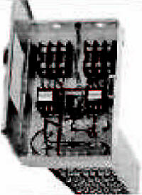
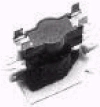
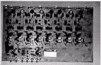
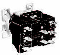
MAGNETIC CONTACTOR
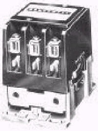
Magnetic contactors (Option B0) are U.L. rated for 100,000 cycle operation and, as standard, are used to deenergize only the circuit. This opens the minimum number of power lines to interrupt the flow of current to the stage of the heater being controlled by that contactor. The number and amperage of the contactors will vary depending upon the KW and voltage. The coil ratings may be 24, 120, 208, 240, or 277 volts. Disconnecting magnetic contactors (Option B6) are so arranged as to break all ungrounded lines. These are standard on 120 volt and 277 volt. This option is necessary when local codes require that contactors break all ungrounded lines. This type of contactor must be used where a Remote Panel (RP) heater is specified.
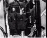
MERCURY CONTACTOR
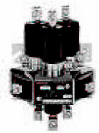
Mercury contactors (Option B3) are usually used where silent operation and/or frequent cycling is desired. The design of the contactor virtually eliminates contact noise and provides for long expectant life under heavy use. Mercury contactors can only be installed in the vertical position. Disconnecting mercury contactors (OptionB3/B6) are also available and must be used when mercury contactors are specified with a Remote Panel (RP) heater.
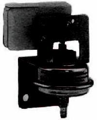
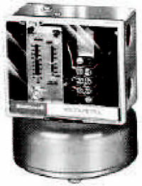
AIR FLOW SWITCH
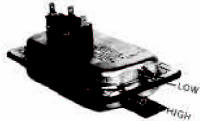
The air flow (pressure) switch (Option C1) is a diaphragm type device that senses the air pressure across the heater surface closing an electrical switch and allowing the heater to be activated. This device assures air flow is present before allowing the heater to energize. The air flow switch is available for either positive or negative air pressure. The pressure differential is .05" + .02". This device is position sensitive and cannot be mounted in a flat horizontal position.
TRANSFORMER
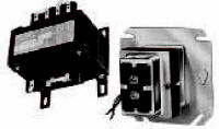
Control transformers are available mounted in the control panel for primary voltage of 120, 208, 240, 277 and 480 with secondary voltages of 24, 120, 208, and 240. A Class II transformer (Option D1) may be used only for 24 volt secondary voltage and only up to 3 steps. All transformers are priced based Ol1 a maximum of 30 AMPS per step. This transformer includes internal primary over current protection. All other transformer- requirements (Option D2) include external primary over current protection. Secondary fusing for use in conjunction with D1 or D2 transformers is available (Option D3).
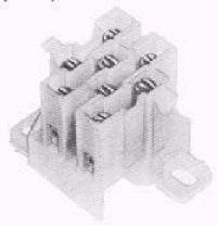
POWER FUSING
U.L. and N.E.C. require that heaters in excess of 48 AMPS be subdivided into branch circuits of 48AMPS or less and be protected by fuses (OptionF1). These are supplied by Warren Manufacturing. If circuit fusing on heaters of 48 AMPS or less is desired price Option F3. For fusing per step (less than 48 AMPS per step) price Option F2. The fewest number of fuse blocks required for the particular KW, AMPS, and Steps will be furnished. The over current protection (fuses) must be sized for 125% of the circuit load.
BACK-UP (SAFETY) CONTACTOR
Back-up contactors (Option B5) are supplied as an addition to the primary controlling contactor or other device and is controlled only by the manual reset cutout. On an over temperature condition, the manual reset opens causing the back-up contactor to be de-energized.
FAN CONNECTION
A set of terminal connections (Option A1) are provided for external connection to the fan circuit. This option is available for line voltage control only. Internal connection can vary and must be specified as to desired method.
THERMAL SAFETY DEVICES
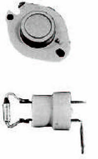
A disc type automatic reset thermal safety cutout that de-energizes the heater element on overheating, and reenergizes the heater element after the temperature has lowered, is provided as standard equipment. The standard cutout temperature is 145°F. A disk type manual reset thermal safety cutout (Option E1, 175° F.) can be provided as a secondary limit control in addition to the standard automatic reset. This device requires a reset button to be engaged to restore power to the heater element. The reset button may be located in the control panel door. A hinged control panel lid is supplied with this option. Also available is a remote manual reset (Option E5) which allows the device to be reset by use of a lock-out circuit utilizing a thermostat or remote switch to reset the limit. A one-time manually replaceable secondary fuse link heat limit is provided as standard equipment. This device is installed in the line side of the heater element and has a standard cutout temperatureof300°F. This device is replaceable without removal of the heater.
DISCONNECT SWITCH
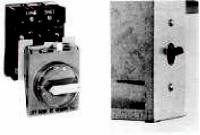
A door-interlocking disconnect switch can be provided to prevent the control panel door from being opened until the power to the heater is disconnected. This switch can be either non-fused (Option J2) or fused (Option J1). A hinged control panel door is standard with this option. A non-door-interlocking panel mount disconnect switch (Option J6) can be provided within the amperage limits listed in the pricing pages. This allows the power to be disconnected independent of the control panel door. A non-hinged control panel door is standard with this option. This disconnect switch can be used in connection with circuit fusing (Option F3) to provide a fused disconnect.
PILOT LIGHTS
Indicator lights may be installed on the side of the control panel to visually show the heater operation mode. Pilot lights available are:
1. Control Circuit On (Option G1)
2. Each Step is On (Option G2)
3. Thermal Cutout is Open (Option G3)
4. Air Switch is Open (Option G4)
SCR CONTROL
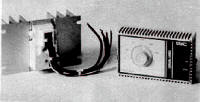
The SCR (Silicone Controlled Rectifier) control (Option L1) is used to provide continuous modulation from zero to the maximum and provides output from the heater in direct proportion to temperature demand. It is available with either a wall mount thermostat or a duct mount thermostat. Temperature can be maintained to within + 1° F of the set point. Back-up contactors (Option B5) and a 24 volt transformer (Option D1/D2) are required with the use of SCR controls. Units over40 AMPS – Vernier type.
TIME DELAY BETWEEN STEPS
To prevent all stages of an electric heater from being energized simultaneously, a time delay relay (Option C2 - nonadjustable or option CA - adjustable) may be employed. This relay will cause a predetermined delay between energizing of each additional stage after the previous stage has been energized.
PILOT RELAY
A pilot relay (Option B2) can be provided where the VA load of the contactor coils exceeds the load capacity of the thermostat or the low voltage transformer. When provided, the pilot relay is controlled by a 24-volt control circuit, which in turn activates the coils of the heater contactors.
PROTECTIVE SCREEN
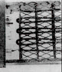
A protective screen (Option V6), that is installed on either the air inlet side or the air outlet side of the heater element, can be provided where it is possible for debris to be in the air stream of the duct and come in contact with the heater elements, or for personal protection. The protective screen is standard on all heaters that are over 48" in either width or height.
P.E. (PNEUMATIC-ELECTRIC) SWITCH
A P.E. Switch (Option C5, C6, C7) is used to change a pneumatic air pressure signal to an electric signal for the control circuit. The thermostat regulates the air pressure signal to the P.E. Switch, which in turn opens and closes regulating the electric signal to the coil of the contactor. A load-carrying P.E. (Option C7) can be provided on most heaters less than 15 AMPS per step, thus eliminating the need for a contactor.
INSULATED CONTROL PANEL
To prevent possible condensation from forming in the heater control panel when the heater is installed in an air conditioning duct, an insulated control panel (Option Q1 ) is often specified. This consists of insulating the outside of the control box closest to the duct to prevent metal contact between the control box and the duct, reducing or eliminating the condensation possibility.
TRANSDUCER
A transducer (Option L3) is used when an SCR control system (Option L1) or electric step controller (Option K1) is required with a pneumatic control system. This device interfaces with the pneumatic system and converts the air pressure changes to the electrical signal needed for the SCR control. This option must be used when an SCR control system is being used in conjunction with a pneumatic control system.
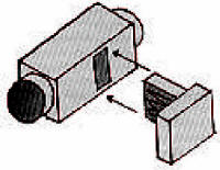
RECESSED TERMINAL BOX
A recessed terminal box (Option V4) is used when a restriction or obstruction may cause a lack of airflow across the electric heater surface. With this option the distance between the control box and the heater element is increased as necessary to avoid the restriction. It is designed to allow the entire element to be exposed to the air flow. The recessed depth can vary as required (1" Standard).
STEP CONTROLLER
A step controller (Option K1) is available for multiple heating stages in a predetermined sequence. The number of steps being energized will be controlled by a proportional thermostat available in either a wall mount or duct mount style. The first stage of the element on is the last stage off. A power failure causes the step controller to recycle from start..
ROUND DUCT CONNECTION
The round duct connection (Option V7) accessory allows an easy method of installing an electric duct heater in a round sheet metal duct. The electric heater section comes factory installed in an adapter section with appropriately sized round pipe connections provided at the inlet and outlet for field connection.
FAN INTERLOCK RELAY
A fan interlock relay (OptionB7) is supplied that utilizes external voltage either from the load side of the fan starter or from the fan control voltage circuit to prevent the heater from operating unless the fan is energized. The interlock voltage must be specified when this option is ordered. This option is often used with continuous fan operation systems.
FAN CONTROL RELAY
A fan control relay (Option B1) energizes the fan simultaneously with the first stage of the heater. It utilizes the heater control circuit to energize the relay, which closes the relay contacts to energize the fan. This option is used where intermittent fan operation is desired. Not available on units with SCR controls.
CIRCUIT BREAKER
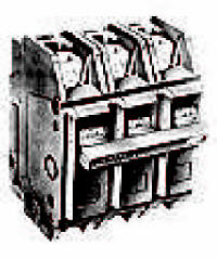
Circuit breakers (Option J3) may be supplied in place of power fusing for over current protection. This device automatically trips to the disconnect (off) position in an over current situation. After correcting the over current situation it can be reset without requiring replacement.
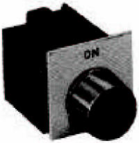
PILOT SWITCH
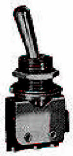
A pilot switch (Option C3, C4) consists of a toggle switch installed on the control panel, that is wired in the control circuit to prevent the energizing of a heater stage (C4), or the entire heater (C3), by de-energizing the control voltage to the contactors. The pilot switch cannot be used as the disconnect switch as required by N.E.C.
|
We are a Distributor of Industrial, Commercial and Residential Heaters and Controls. Always consult manufacturers installation instructions for proper installation of the products or systems shown on this website. © Copyright 1999-2019 Mor Electric Heating Assoc., Inc. MOR
ELECTRIC HEATING ASSOC., INC. |
| |